


Overview
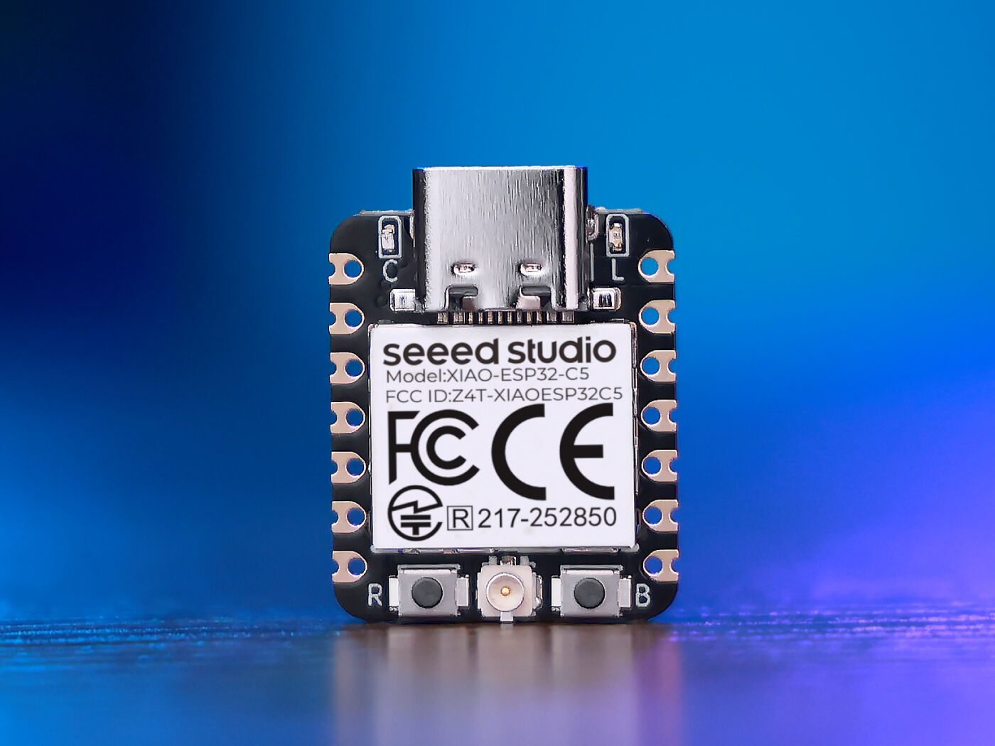
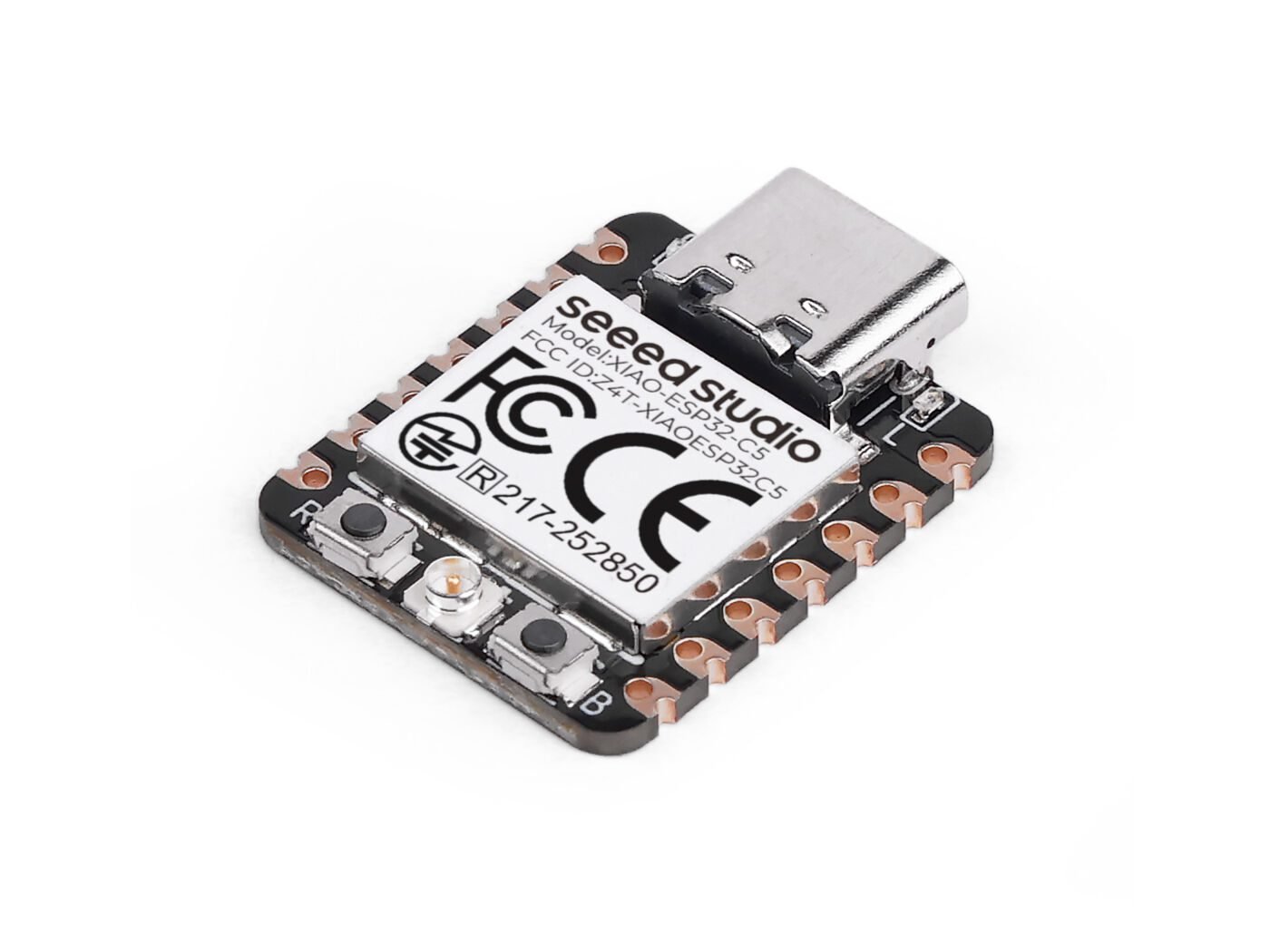
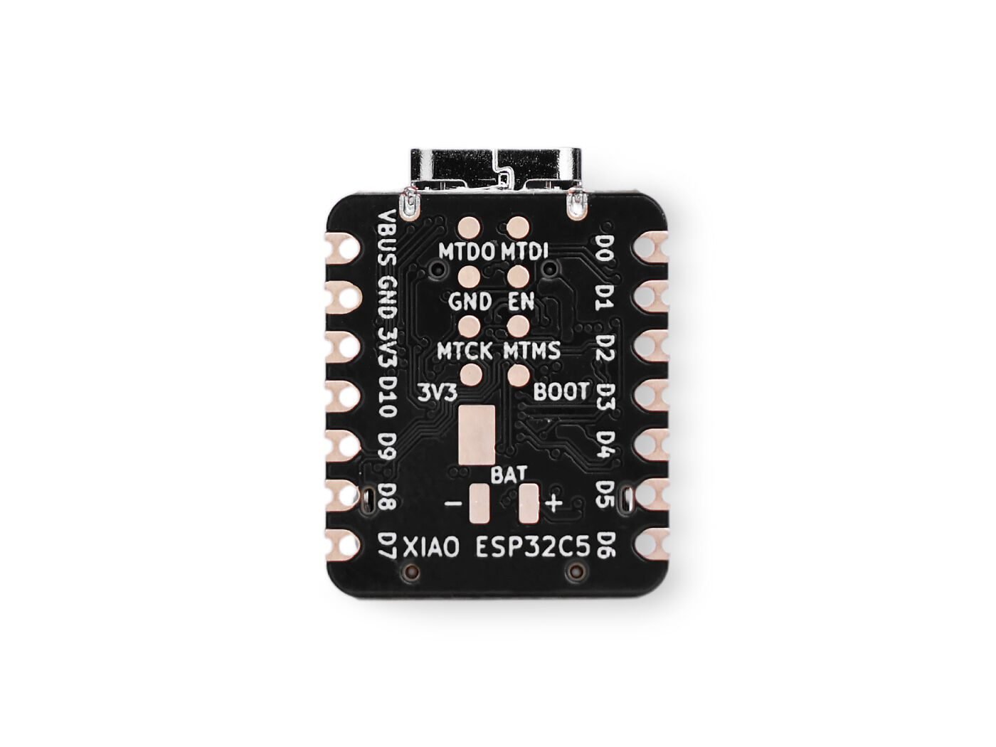
ESP32-C5 is a compact development board with 2.4 GHz and 5 GHz dual-band Wi-Fi 6, Bluetooth 5 (LE), and IEEE 802.15.4 connectivity. It combines a RISC-V processor running at up to 240 MHz with 8 MB Flash and 8 MB PSRAM. Application protocols and services depend on the selected SDK, firmware, and integration.
Single Pack: Includes 1 ESP32-C5 board, 1 FPC antenna, and 2 pin headers. A practical choice for getting started and prototyping.
Key features
Choose Your Packaging
The same ESP32-C5 hardware is available in three packaging options. This page is the Single Pack: 1 board, 1 FPC antenna, and 2 pin headers.
- Single Pack: 1 board, 1 FPC antenna, and 2 pin headers for individual prototypes.
- 3-Pack: 3 boards, 3 FPC antennas, and 6 pin headers for multi-node projects.
- Tape & Reel: production packaging. Confirm the reel quantity, ordering unit, minimum order, order increments, and included accessories before ordering.
Start Building
Follow the Getting Started guide for setup and hardware resources, then check the pin-multiplexing guide for interfaces and wiring.
- First Studio with 5 GHz Wi‑Fi
Provides dual‑band Wi‑Fi 6 for cleaner spectrum access and higher throughput in 5 GHz, while maintaining 2.4 GHz compatibility.
- Comprehensive connectivity
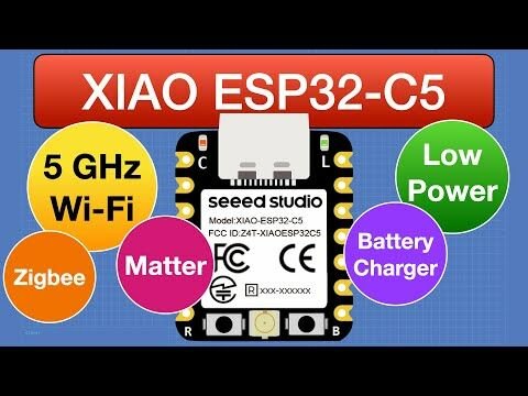
Dual-band Wi-Fi 6, Bluetooth 5 (LE), and IEEE 802.15.4 provide the hardware connectivity for IoT development. Matter, HomeKit, and MQTT applications require a compatible SDK, firmware, or integration; availability and setup depend on the chosen software stack.
- High‑performance core
Equipped with a 32‑bit RISC‑V single‑core processor running up to 240 MHz, the ESP32‑C5 integrates 384 KB on‑chip SRAM, 320 KB ROM, 8MB Flash, and 8MB PSRAM. This combination ensures smooth protocol handling, multitasking, and application scalability.
- Enhanced security
Secure boot, flash encryption, and hardware cryptographic accelerators to protect firmware and data integrity.
- Built‑in Battery Interface for Low‑Power Designs
Integrated battery management supports low-power designs. Typical deep-sleep current with low-power firmware is 15 µA when powered through BAT and 375 µA when powered through USB. Actual consumption depends on firmware, supply, and connected peripherals.
Unlock the Full Potential with Add-ons
The series is powerful on its own, but it becomes unstoppable when paired with our diverse lineup of Add-on boards. Designed to bridge the gap between a raw microcontroller and a finished project, these add-ons cater to every need: from Expansion Board—which adds an OLED screen, RTC, and battery management—to specialized functional modules like Wi-Fi HaLow and LoRa (SX1262) for long-range connectivity, LED Driver Board/COB LED Driver Board for lighting applications, or ePaper Driver Boards compatible with various display sizes for ultra-low power visual interfaces. Dive into our extensive modules to discover even more ways to expand your.
We already have over 15 products based on different solutions in the family, to help you better understand the differences and choose the most suitable part for your projects, please refer to the Series Page.
Starter Kit with free Course for all Electronics Neophytes and Enthusiasts
Not only programming but also electronics knowledge is not required, you will be taken step by step, from understanding the basic concepts to exercising the simple projects individually, finally being able to build complex, interesting, wearable projects on your own, owing a practical electronic product prototype from the course.
Debug Mate supports UART serial monitoring and power-consumption analysis with ESP32-C5. Its DAPLink/SWD chip-level debugging feature does not support the ESP32-C5 RISC-V core. See the compatibility guide before selecting a debugging setup.
Production-Ready Design with Fusion PCBA Support
All dev boards feature a production-optimized SMD (Surface Mount Device) design with standardized stamp holes, making it perfect for commercial PCBA (Printed Circuit Board Assembly) integration.
With our Fusion services, you can access competitive one-stop PCBA manufacturing, component sourcing, and testing, plus free DFA/DFM review to reduce manufacturing risks and accelerate the journey from prototype to production.
Note
SoM User Manual open-sources all hardware and software materials, providing professional product design guidelines to help you accelerate ideas off the ground, streamline product design, providing a seamless experience from module selection to mass production. You can check here to see more info.
Specification
Product | ESP32-C5 |
|---|---|
Chipset | ESP32-C5HR8 |
Processor | High-performance 32-bit RISC-V single-core microprocessor, up to 240 MHz, with a low-power 32-bit RISC-V core. |
SRAM | 384KB |
PSRAM | 8MB |
Flash | 8MB |
Interface | 11x GPIO Pin |
1x Analog Pin + 4x Analog Pad on the reverse side | |
1x I2C | |
1x UART | |
1x SPI | |
1 x JTAG (Pads on the reverse side) | |
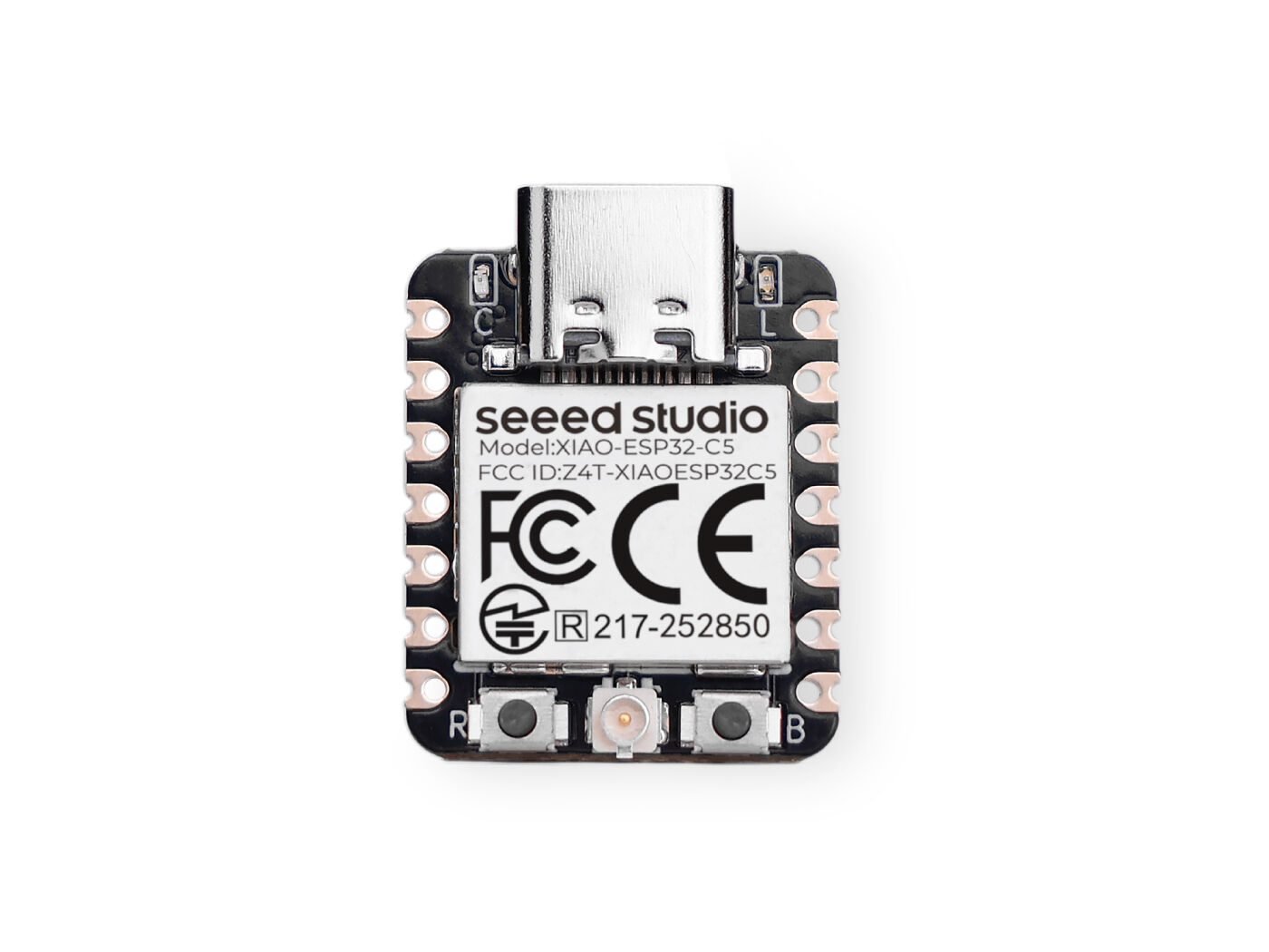
On Board | 1x User LED (Green) |
1x Charge LED (Battery Charging Indicator) | |
1x Reset Button | |
1x Boot Button | |
1x UFL Connector | |
Antenna | FPC Antenna – A01(2.80 dBi) Optional: 2.4GHz Rod Antenna (2.81dBi) — 2.4 GHz only; not suitable for 5 GHz operation. |
Wireless Connectivity | 2.4 and 5 GHz dual-band Wi-Fi 6 (802.11ax) |
Bluetooth® 5 (LE) | |
Zigbee | |
Thread (802.15.4) | |
Power Input | Type-C: 5V/DC |
Battery: 3.7V | |
Deep Sleep(Typ.) (Low Power Firmware) | USB Power Supply: 375 µA Battery Power (BAT): 15 µA |
Working Temperature | 0°C ~85°C |
Dimensions | 21 x 17.8mm |
Application
- Smart Sensor Node
- IoT Gateway
- BLE Tracker
- Wi-Fi Button
- Secure Edge Device
- Smart Home Automation Device
- Wireless Security Testing
Hardware overview
Note: ESP32-C5 supports dual-band Wi-Fi with certification coverage for W52, W53, and W56. Optimized for indoor environments, with outdoor deployment available upon inquiry.
Part list
ESP32-C5 | x1 |
FPC Antenna | x1 |
Pin Header | x2 |




Reviews
There are no reviews yet.